Hunter Rideout
Buggies Project Portfolio
HOME Resume About Me
BuggiesProject Portfolio
Hunter Rideout
HOMEResumeAbout Me
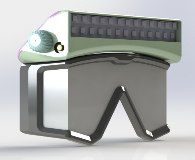
 CAD design starts with the modeling of my scuba mask and selection of the electronic components
 CAD design starts with the modeling of my scuba mask and selection of the electronic components

CAD design starts with the modeling of my scuba mask and selection of the electronic components
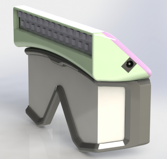
 I next create the basic shape and boundaries of the enclosure limited by the mask and the diver’s face.  The electronics are then positioned as compactly as possible while still allowing for soldering

I next create the basic shape and boundaries of the enclosure limited by the mask and the diver’s face. The electronics are then positioned as compactly as possible while still allowing for soldering
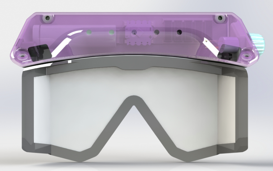
 The model is then detailed with holes for fasteners, pour holes, and weep holes for the resin, as well as locating features for the electronics

The model is then detailed with holes for fasteners, pour holes, and weep holes for the resin, as well as locating features for the electronics

 After ensuring that the circuit works properly as designed and that our microcontroller is programmed properly, we are ready to prep the components for assembly
After ensuring that the circuit works properly as designed and that our microcontroller is programmed properly, we are ready to prep the components for assembly

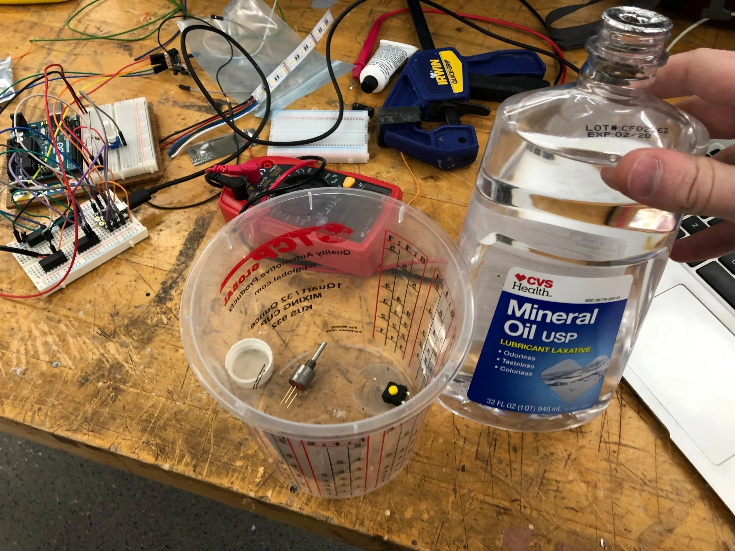
 Using mineral oil (non-conductive, non-corrosive, and effectively incompressible) to replace the air inside of the potentiometer and toggle button
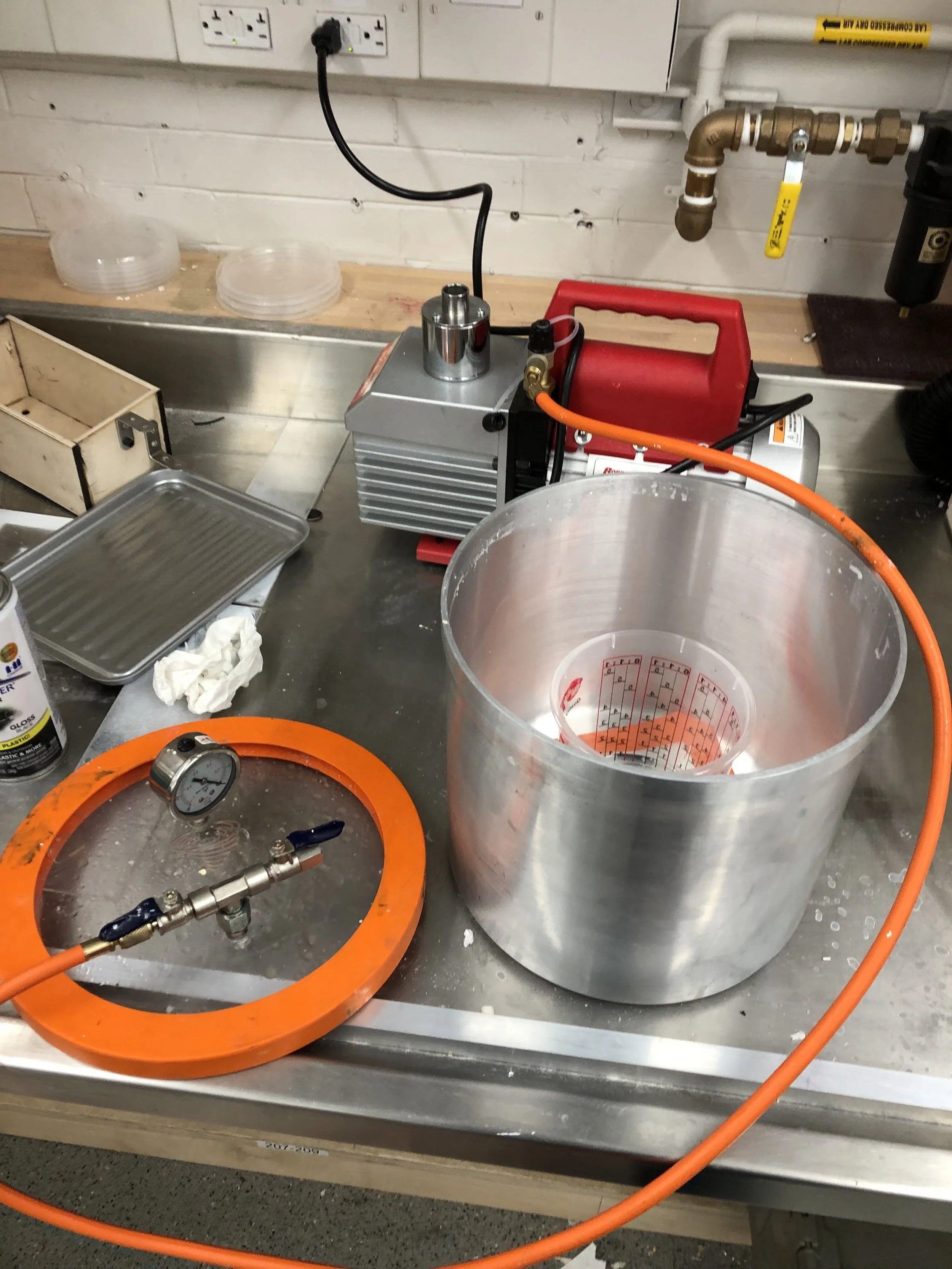
Using mineral oil (non-conductive, non-corrosive, and effectively incompressible) to replace the air inside of the potentiometer and toggle button

 This requires using a vacuum pump to pull the air out while the parts are submerged in the oil

This requires using a vacuum pump to pull the air out while the parts are submerged in the oil

 We can see the air bubbles that have escaped the parts after the vacuum
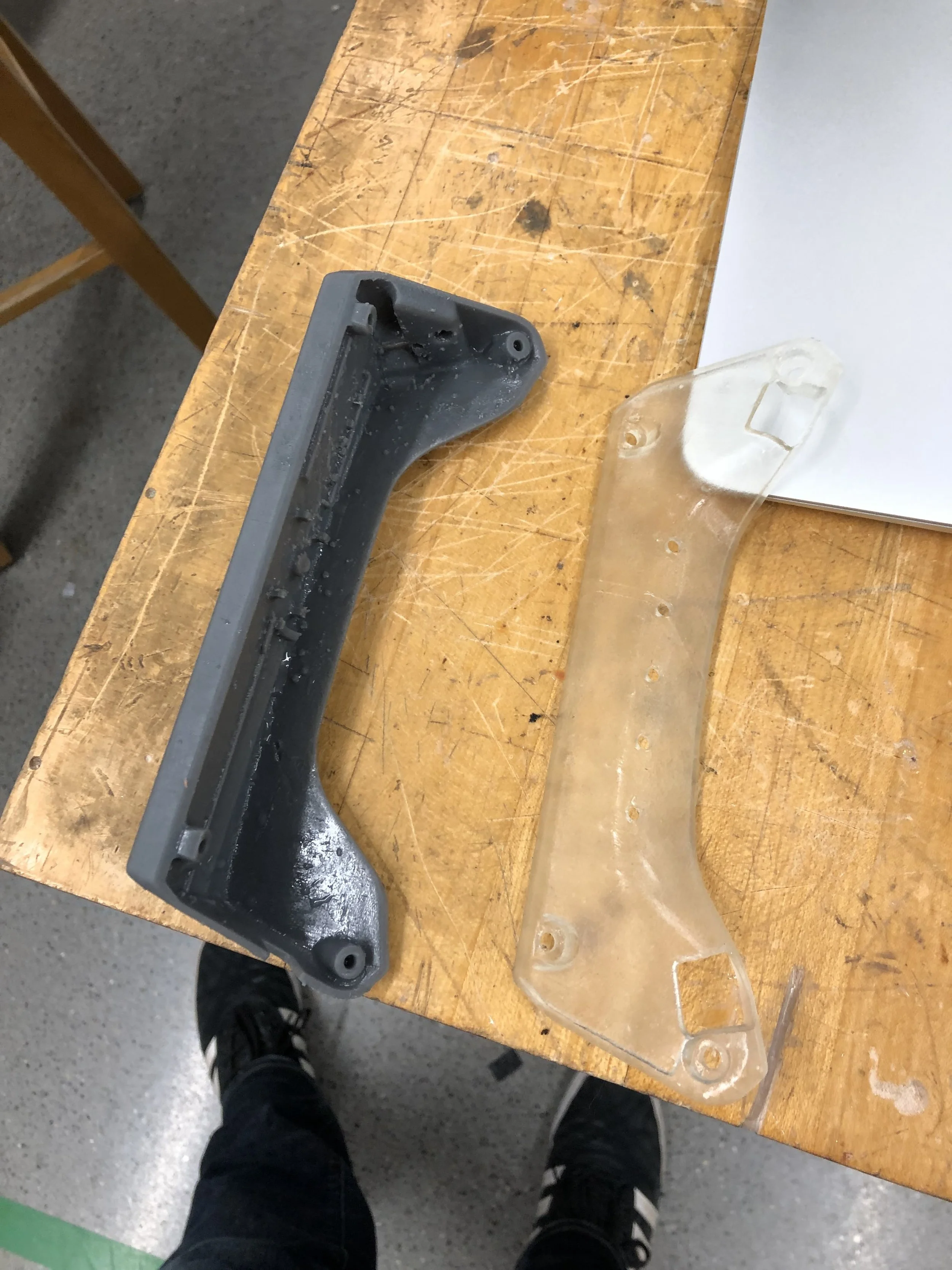
We can see the air bubbles that have escaped the parts after the vacuum

 The enclosure halves fresh off the 3D printer.  The front half (left) has all of the component mounting

The enclosure halves fresh off the 3D printer. The front half (left) has all of the component mounting
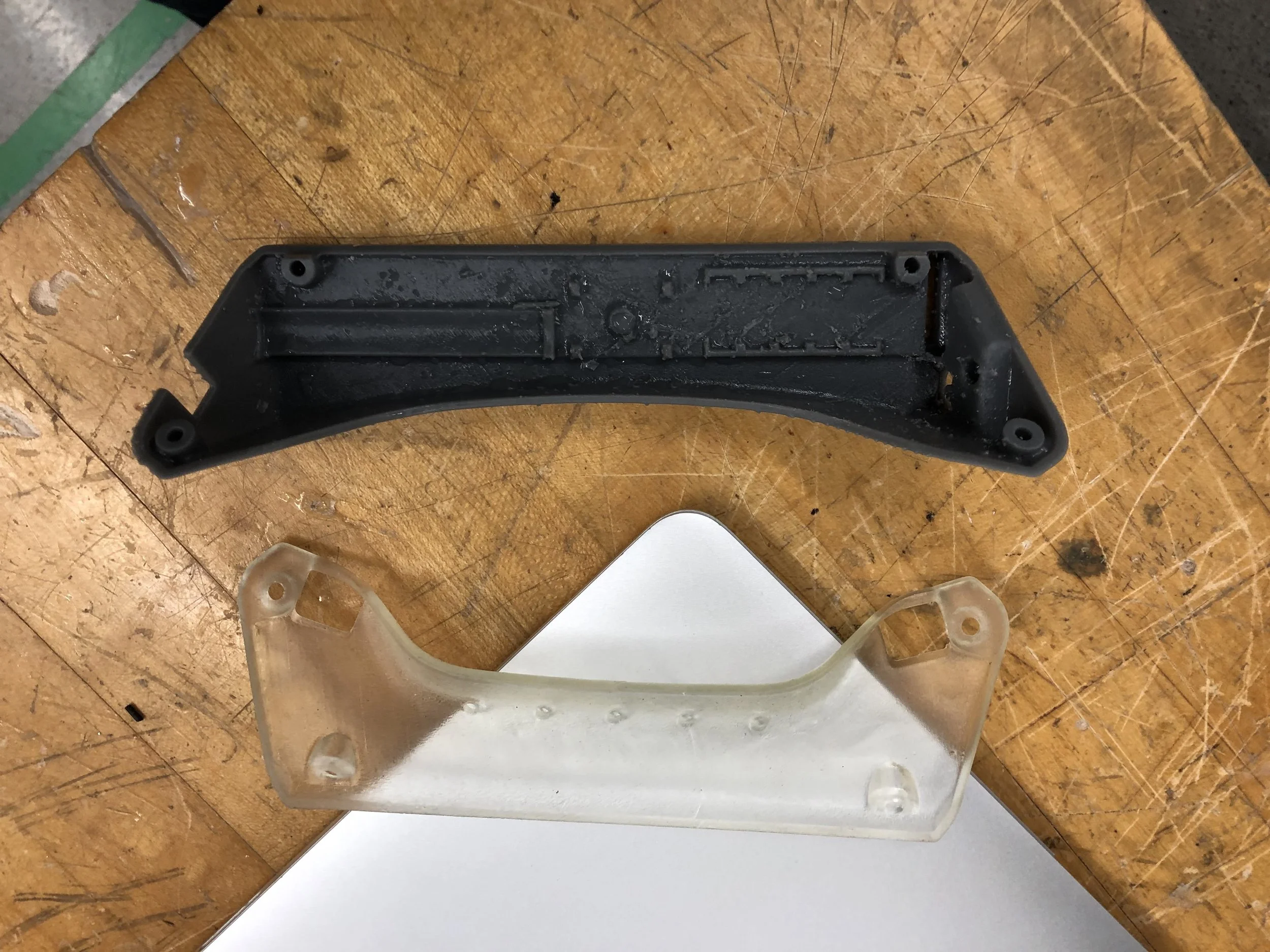
 The front is opaque to funnel all of the light from the LEDs in the direction of the diver’s focus.  The back panel is clear to give an interesting view of the electronics through the clear resin potting
The front is opaque to funnel all of the light from the LEDs in the direction of the diver’s focus. The back panel is clear to give an interesting view of the electronics through the clear resin potting

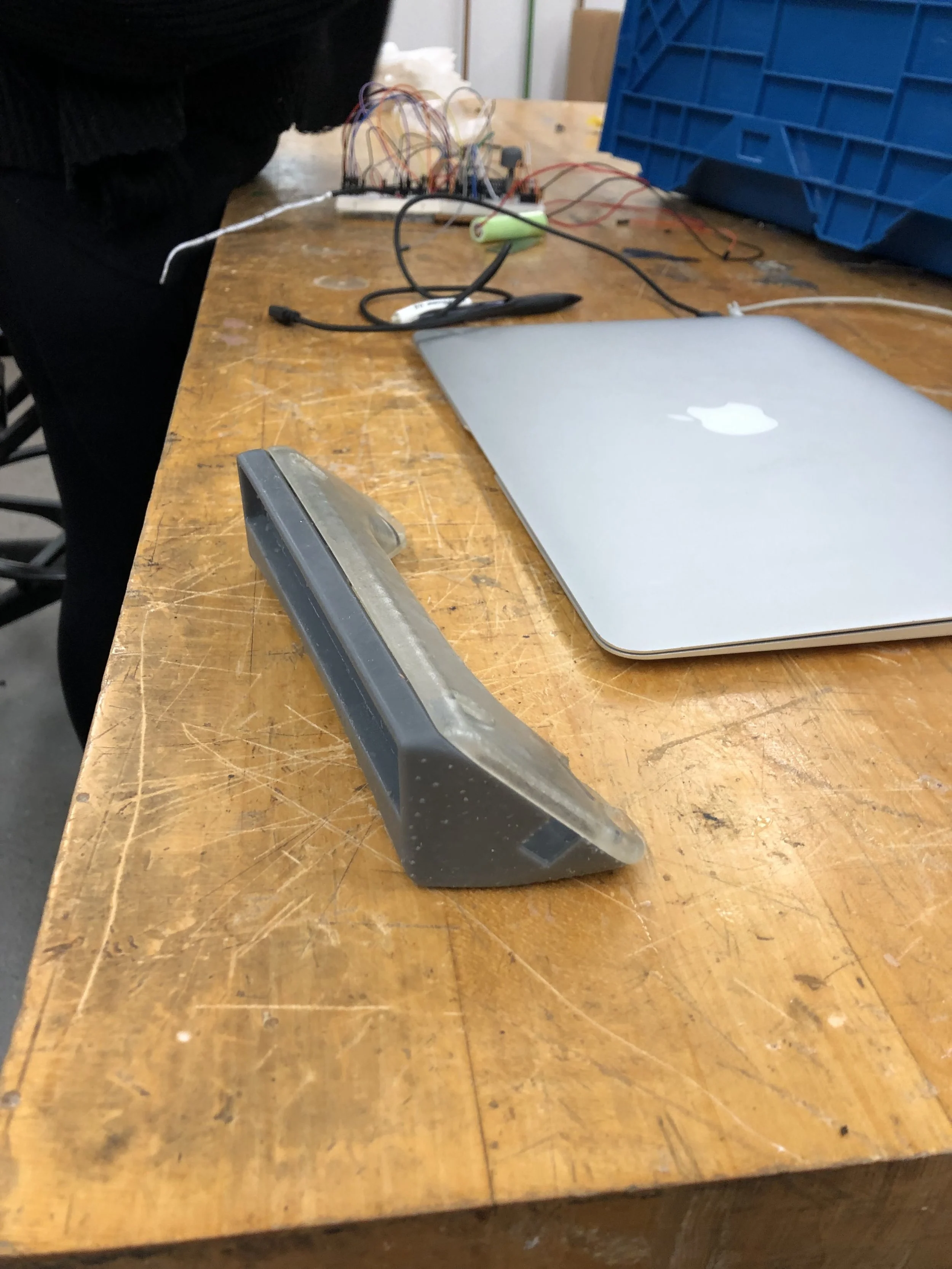
 A first look at the finished shape
A first look at the finished shape

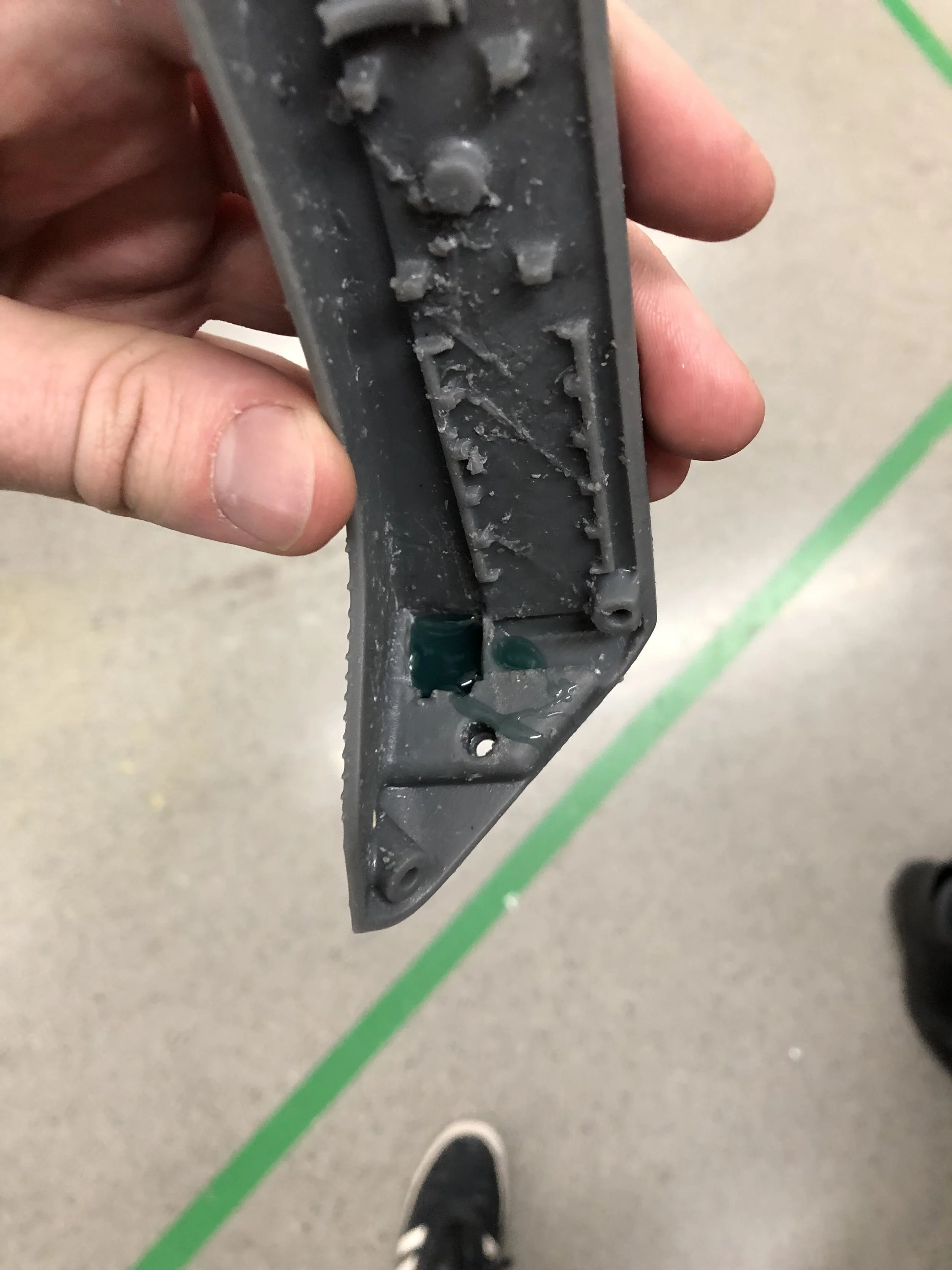
 Flexible urethane is poured into the button area to seal the enclosure while still allowing the button to be actuated

Flexible urethane is poured into the button area to seal the enclosure while still allowing the button to be actuated

 In the top of the image is the power button mold used to form the exterior shape (the interior shape is formed using an extra button covered in mold release).  The gap where the LED strip leads connect to the interior of the enclosure is filled with

In the top of the image is the power button mold used to form the exterior shape (the interior shape is formed using an extra button covered in mold release). The gap where the LED strip leads connect to the interior of the enclosure is filled with fast curing silicone caulk to prevent the potting resin from dripping through
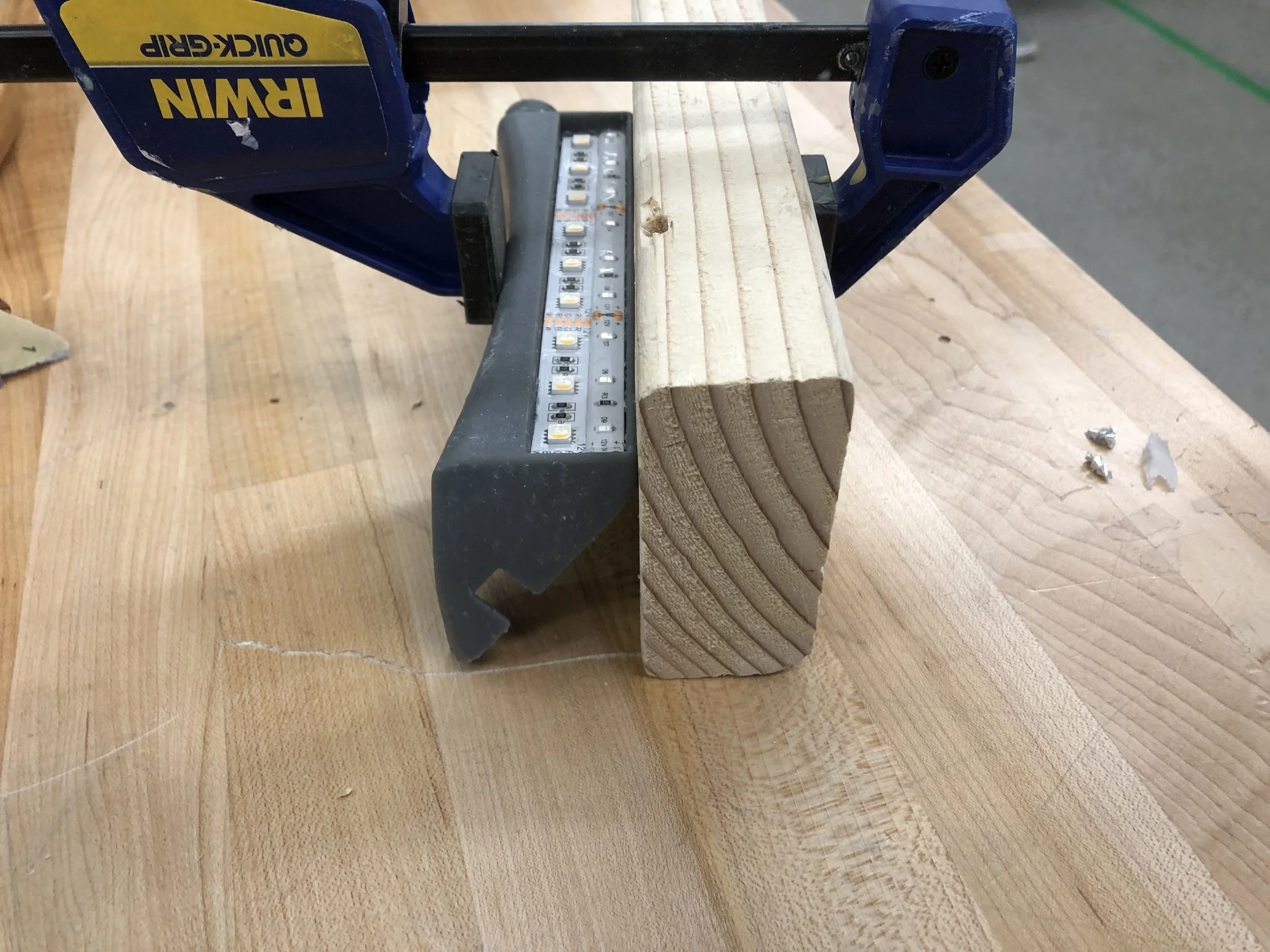
 The whole part is clamped level and the resin is poured
The whole part is clamped level and the resin is poured

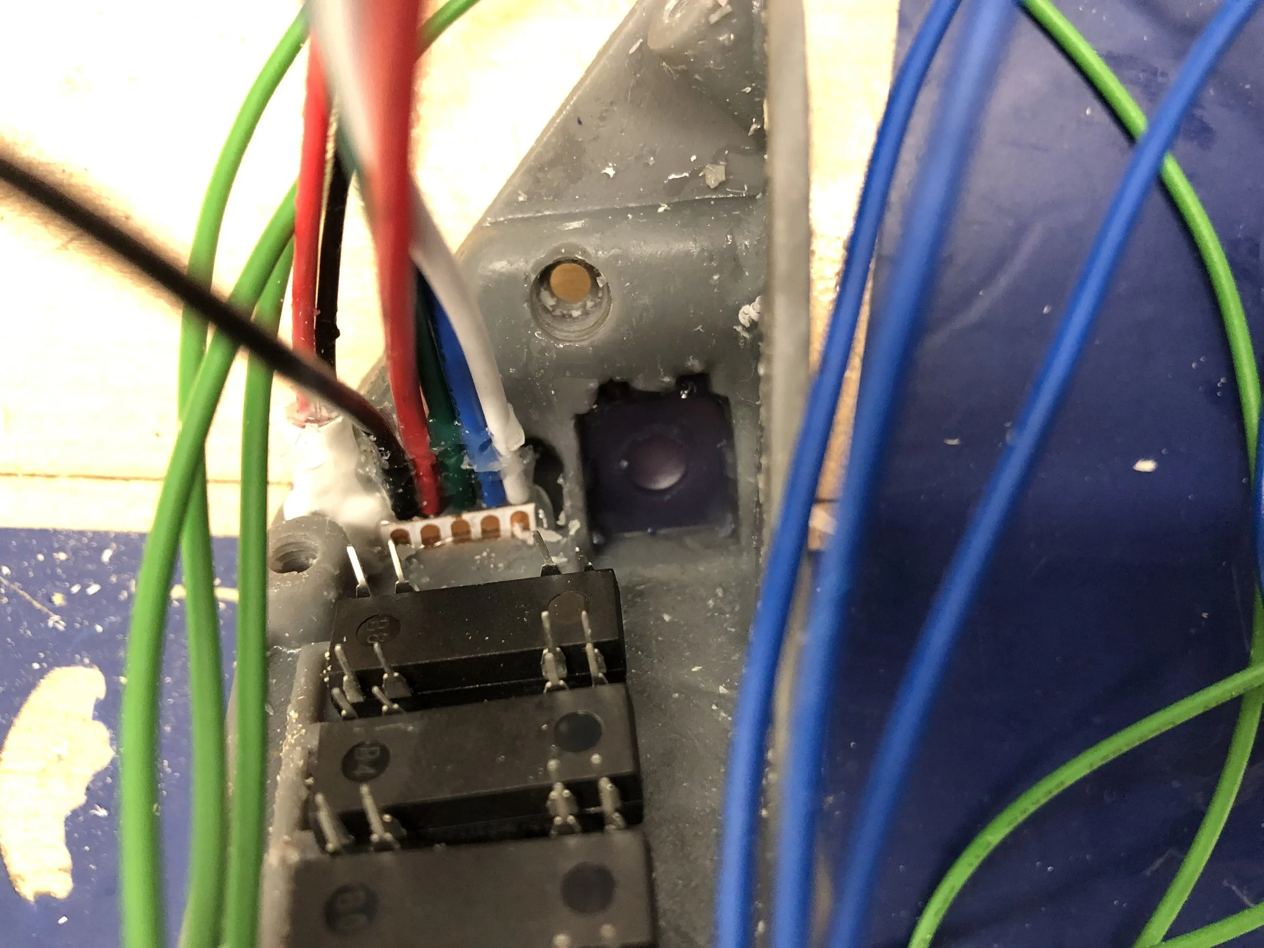
 A look at the inside of the button after a few electronics have been mounted
A look at the inside of the button after a few electronics have been mounted

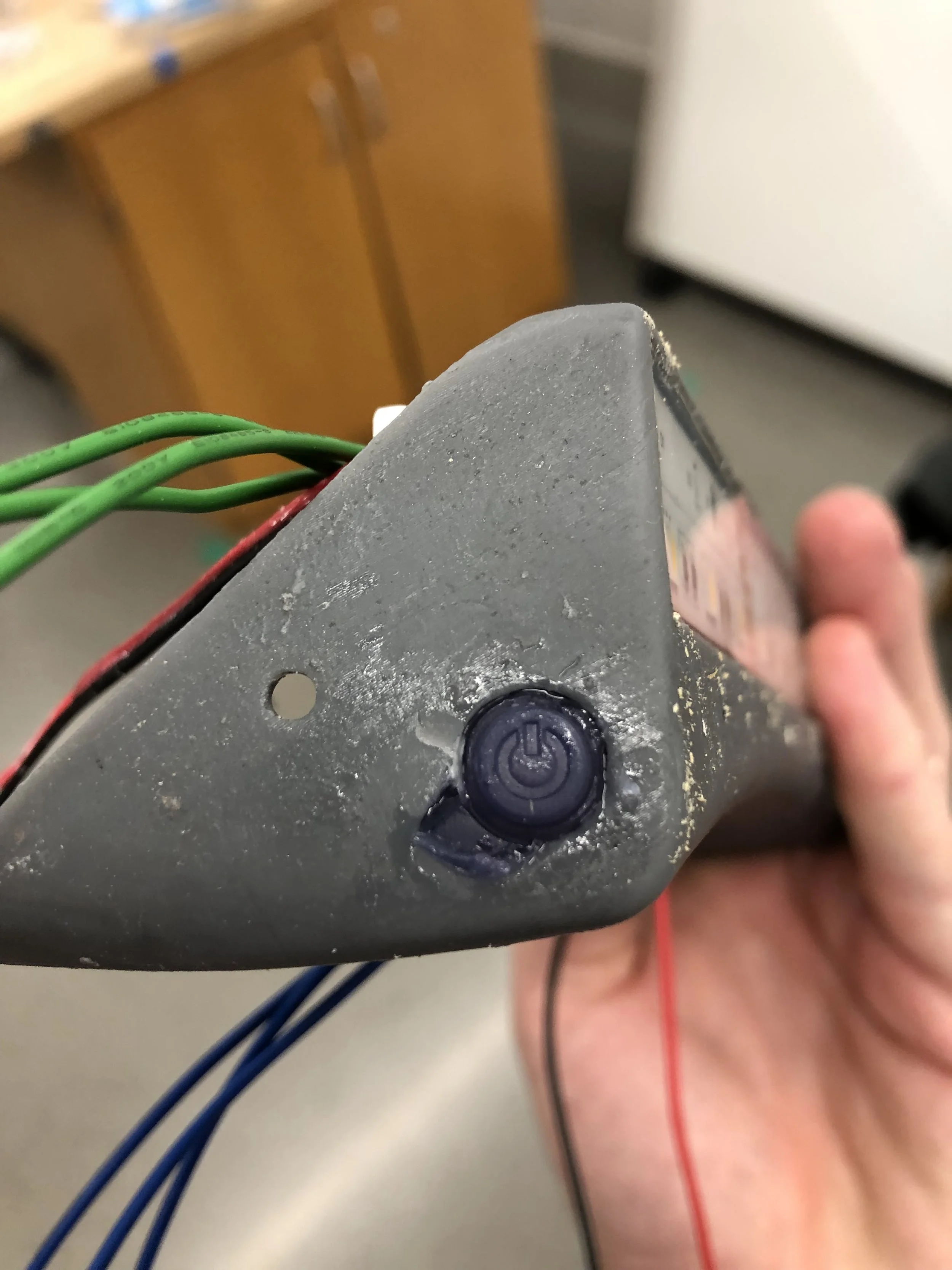
 WE HAVE A BUTTON!  A small section of the enclosure was accidentally chipped off while removing some of the support material that was blocking the button cavity

WE HAVE A BUTTON! A small section of the enclosure was accidentally chipped off while removing some of the support material that was blocking the button cavity

 The components are tacked onto their locating features with superglue whale things get soldered
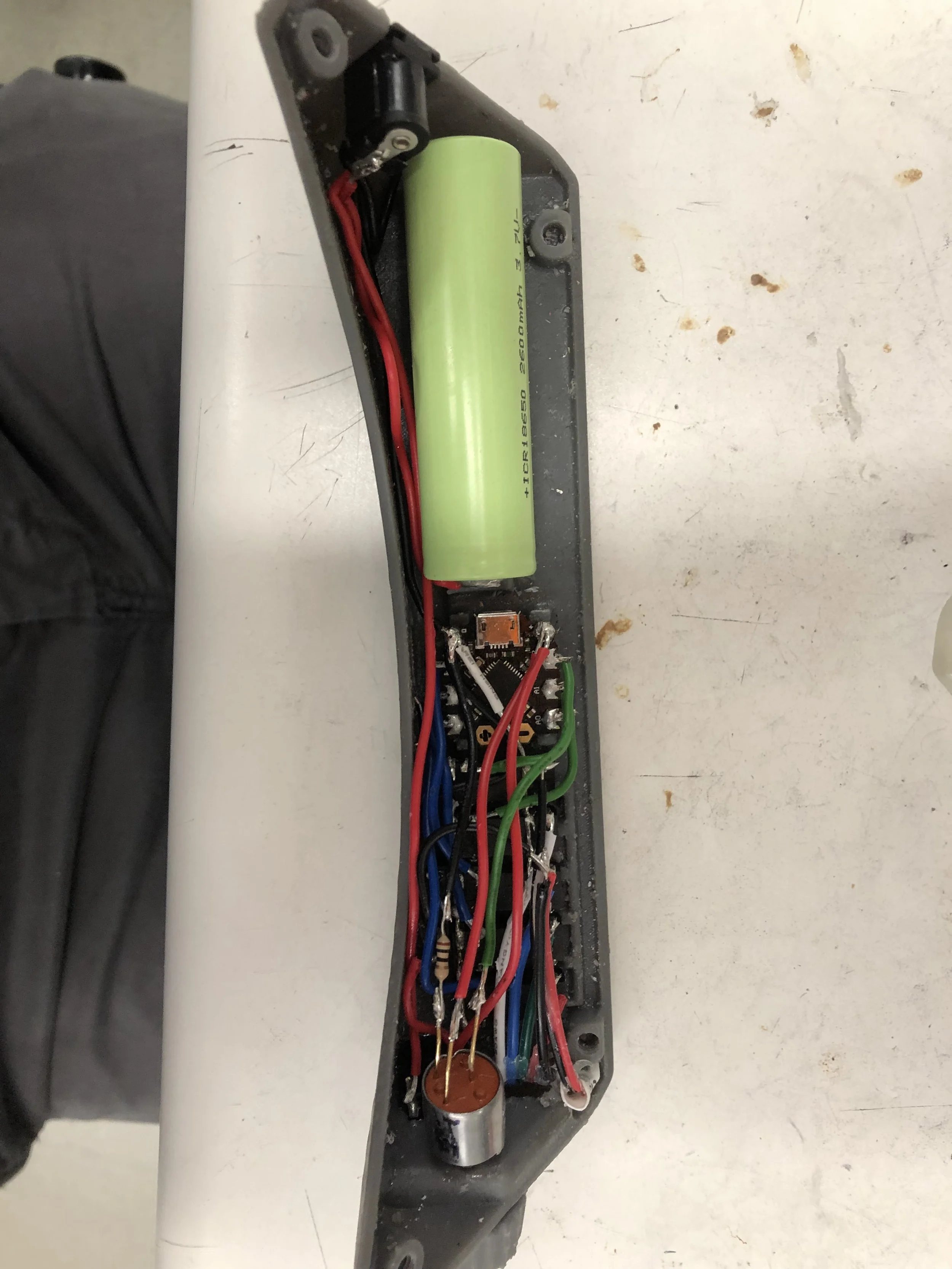
The components are tacked onto their locating features with superglue whale things get soldered

 With wire lengths trimmed and the board accidentally shorted, the white light turns on and the assembly is ready to be enclosed and potted
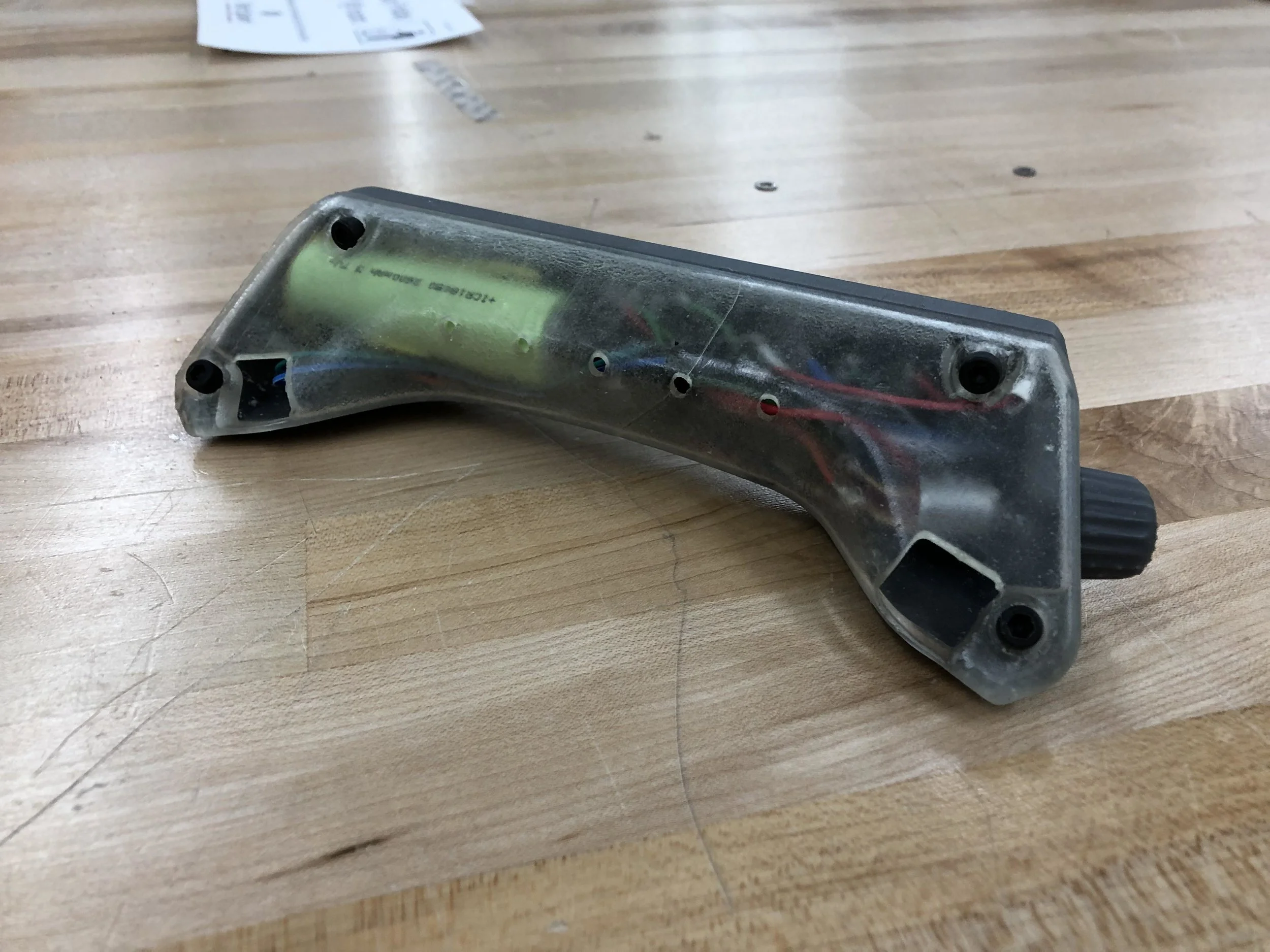
With wire lengths trimmed and the board accidentally shorted, the white light turns on and the assembly is ready to be enclosed and potted

 With fasteners added, the enclosure is ready for resin!

With fasteners added, the enclosure is ready for resin!

 There were some small gaps along the enclosure seams that needed to be sealed with tape
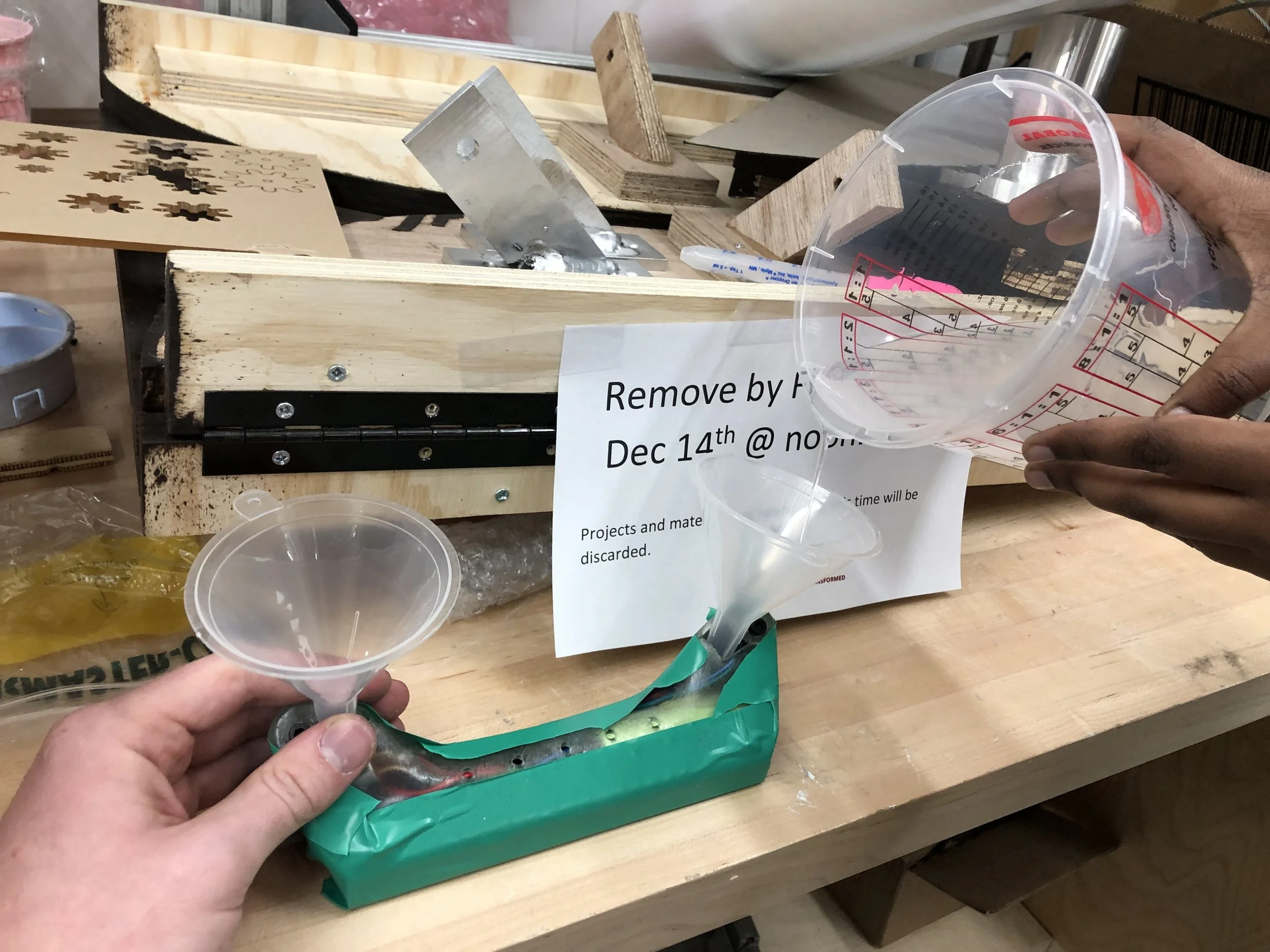
There were some small gaps along the enclosure seams that needed to be sealed with tape

 And the resin is poured!  After the resin just reaches the weep holes (so we don’t trap any air bubbles) we covered them with tape and filled the rest of the enclosure.  The entire assembly was placed into a 90psi pressure pot to force any bubbles i

And the resin is poured! After the resin just reaches the weep holes (so we don’t trap any air bubbles) we covered them with tape and filled the rest of the enclosure. The entire assembly was placed into a 90psi pressure pot to force any bubbles in the resin to be smaller during curing

 Finished power button and color selection dial
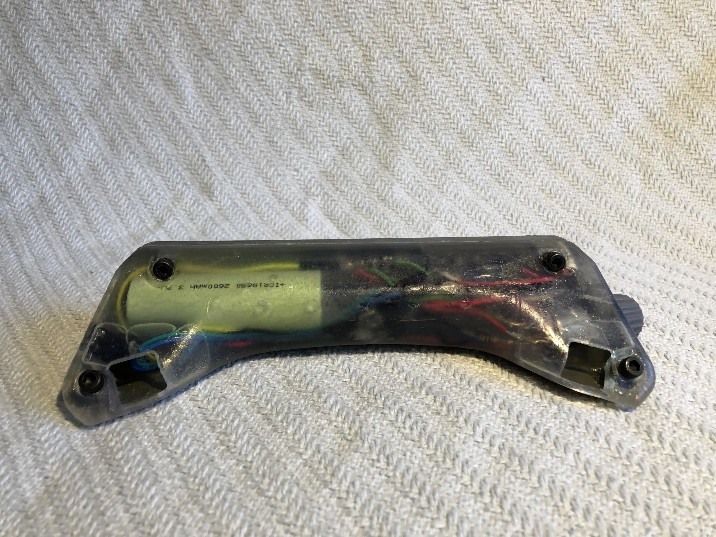
Finished power button and color selection dial

 A look at the electronics

A look at the electronics

 The power jack is plugged with a hand carved plastic nib

The power jack is plugged with a hand carved plastic nib

 With all the components jammed inside, the overall product is pretty sleek!

With all the components jammed inside, the overall product is pretty sleek!

 LET THERE BE LIGHT

LET THERE BE LIGHT

 A look at how the light may be used underwater.  More impressive testing pictures to come on my next dive trip

A look at how the light may be used underwater. More impressive testing pictures to come on my next dive trip

 Looking pretty slick!

Looking pretty slick!

 Scuba diver for scale

Scuba diver for scale

 Making steps from concept development…

Making steps from concept development…

 To reality!

To reality!

1 2 3 4 5 6 7 8 9 10 11 12 13 14 15 16 17 18 19 20 21 22 23 24 25 26 27 28 29 30
Previous Next
 CAD design starts with the modeling of my scuba mask and selection of the electronic components
 I next create the basic shape and boundaries of the enclosure limited by the mask and the diver’s face.  The electronics are then positioned as compactly as possible while still allowing for soldering
 The model is then detailed with holes for fasteners, pour holes, and weep holes for the resin, as well as locating features for the electronics
 After ensuring that the circuit works properly as designed and that our microcontroller is programmed properly, we are ready to prep the components for assembly
 Using mineral oil (non-conductive, non-corrosive, and effectively incompressible) to replace the air inside of the potentiometer and toggle button
 This requires using a vacuum pump to pull the air out while the parts are submerged in the oil
 We can see the air bubbles that have escaped the parts after the vacuum
 The enclosure halves fresh off the 3D printer.  The front half (left) has all of the component mounting
 The front is opaque to funnel all of the light from the LEDs in the direction of the diver’s focus.  The back panel is clear to give an interesting view of the electronics through the clear resin potting
 A first look at the finished shape
 Flexible urethane is poured into the button area to seal the enclosure while still allowing the button to be actuated
 In the top of the image is the power button mold used to form the exterior shape (the interior shape is formed using an extra button covered in mold release).  The gap where the LED strip leads connect to the interior of the enclosure is filled with
 The whole part is clamped level and the resin is poured
 A look at the inside of the button after a few electronics have been mounted
 WE HAVE A BUTTON!  A small section of the enclosure was accidentally chipped off while removing some of the support material that was blocking the button cavity
 The components are tacked onto their locating features with superglue whale things get soldered
 With wire lengths trimmed and the board accidentally shorted, the white light turns on and the assembly is ready to be enclosed and potted
 With fasteners added, the enclosure is ready for resin!
 There were some small gaps along the enclosure seams that needed to be sealed with tape
 And the resin is poured!  After the resin just reaches the weep holes (so we don’t trap any air bubbles) we covered them with tape and filled the rest of the enclosure.  The entire assembly was placed into a 90psi pressure pot to force any bubbles i
 Finished power button and color selection dial
 A look at the electronics
 The power jack is plugged with a hand carved plastic nib
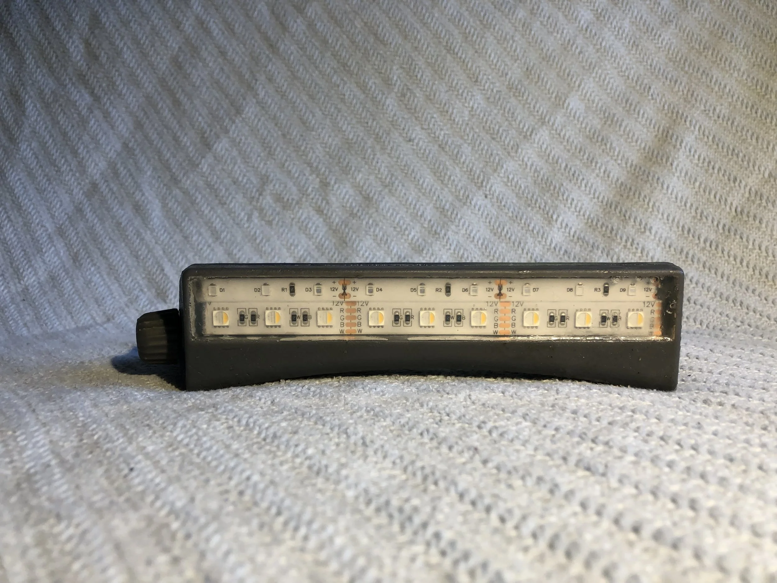
 With all the components jammed inside, the overall product is pretty sleek!
 LET THERE BE LIGHT
 A look at how the light may be used underwater.  More impressive testing pictures to come on my next dive trip
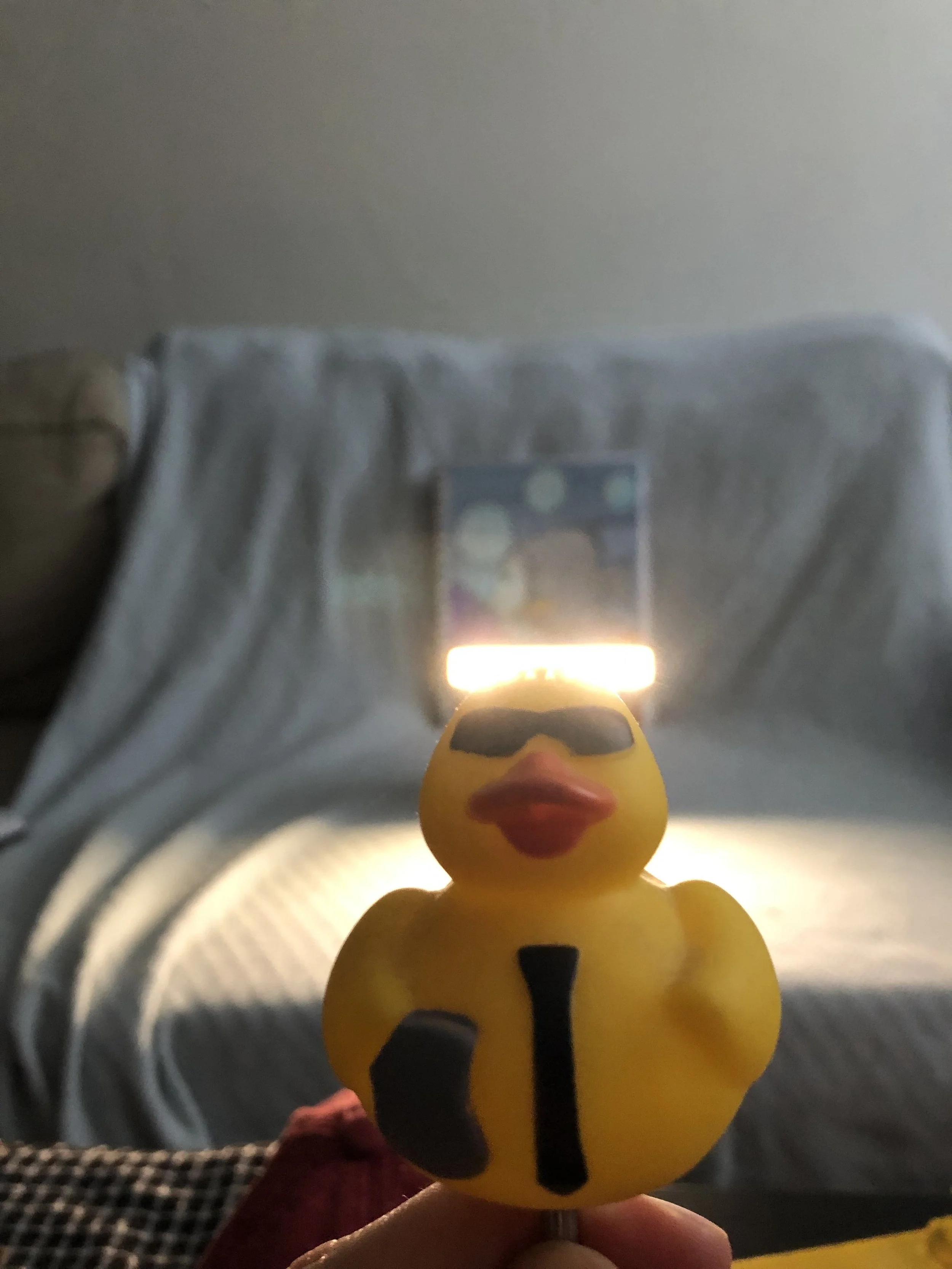
 Looking pretty slick!
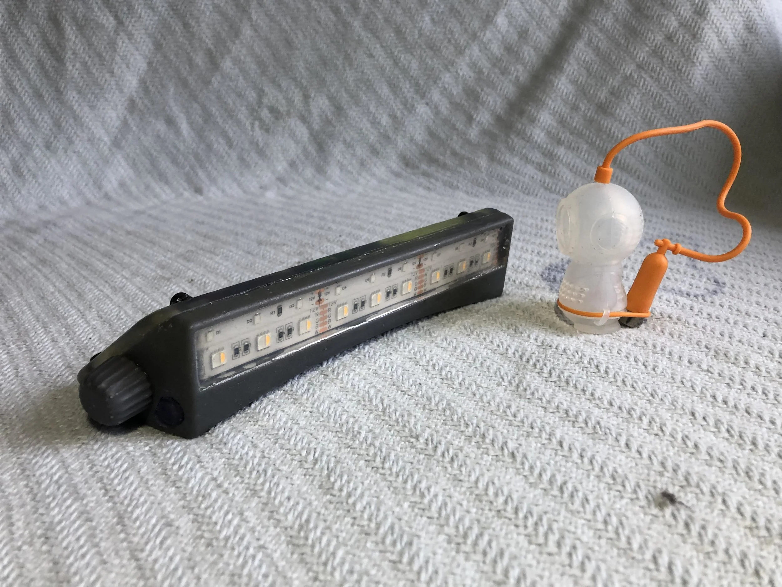
 Scuba diver for scale
 Making steps from concept development…
 To reality!
R-logo-white.png

(828)-514-5442 • rideouthtr@gmail.com